
JAEMAN ALEX CHOI

MECHANICAL ENGINEERING: INJECTION MOLDING
WINTER 2020
PROJECT OVERVIEW
This manufacturing project entails a multi stage process of producing a plastic injected mold inspired from a 4th grade student's drawing. Before projecting the 4th grader’s illustration into Siemens NX Lab, my team of three sketched our own design with considerations of manufacturing feasibility. After iterations of analyzing our CAD design features and implementing modifications when necessary, we were able to produce a manufacturing program in the software; we transferred the G-code to the CNC Machine to produce a CNC Drilled cavity and core mold, which we then used to inject plastic to create our toy robot. This project required both strategic planning and the patience of iterative mechanical design. The process walked me through the phases of bringing an idea of form into life using computer aided drawing and manufacturing operations as well as the fundamentals of injection molding, which is the liaison to mass production. As an action figure fanatic, learning how my old toys were made was intrinsically satisfying, and it has motivated me to be more inclined to learn how other things are created as well.
10 WEEKS
PERSONAL RESPONSIBILITIES
-
Helped design part and identify constraints in manufacturing feasibility
-
Created CAD of parts; core and cavity mold of arm and mohawk
-
Created CAM instructions for parts; core and cavity mold of arm and mohawk
-
Machined core and cavity mold of arm/mohawk using CNC Machine
-
Injection Molding of Arm/Mohawk mold.
SKILLS

Computer Aided Drawing
CNC Milling Machine

Injection Molding

PART DESIGN
Our part design evolved from a simple sketch to a fully manufacturable, injection feasible mold. Each part took into consideration the fundamental features of injection molding such as uniform wall thickness, draft while avoiding sliding shut offs, sharp corners, and undercuts amongst others. Our part and assembly design resulted in four main parts: the robot body and head, each of the robot arms, and finally the iconic Mohawk. It is essential to note that each of the left and right arm parts are the conjunction of two halves.
In order to execute our design, we needed to also have mating parts. For each arm piece– a male pin and female hole – were created with the use of snap fit assembly with minimal interference to have a desired fit. Since our bosses dealt with small sizes of up to 1/16th inch hole, we pursued the use of dowel pins to manufacture the preferred extrusion.
The CAD drawing of the core and cavity molds for the mohawk and arm parts are depicted below.


MOLD DESIGN
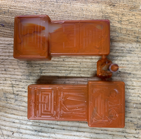
An aesthetic factor determined the positioning of our parting line for the body and arm mold - it is not visible from the front view of the toy. The orientation of the parts in the mold were positioned as photographed below.


Body Mold:
The body mold consisted of the front and back of our main piece with precisely drilled holes in the corners to avoid sink marks and also to ensure the fit of dowels pins which are used to define the hole features during injection. The distance from the sprue to the the widest surface of the cavity/core part was kept consistent to encourage uniform injection and cooling.
Arms and Mohawk Mold:


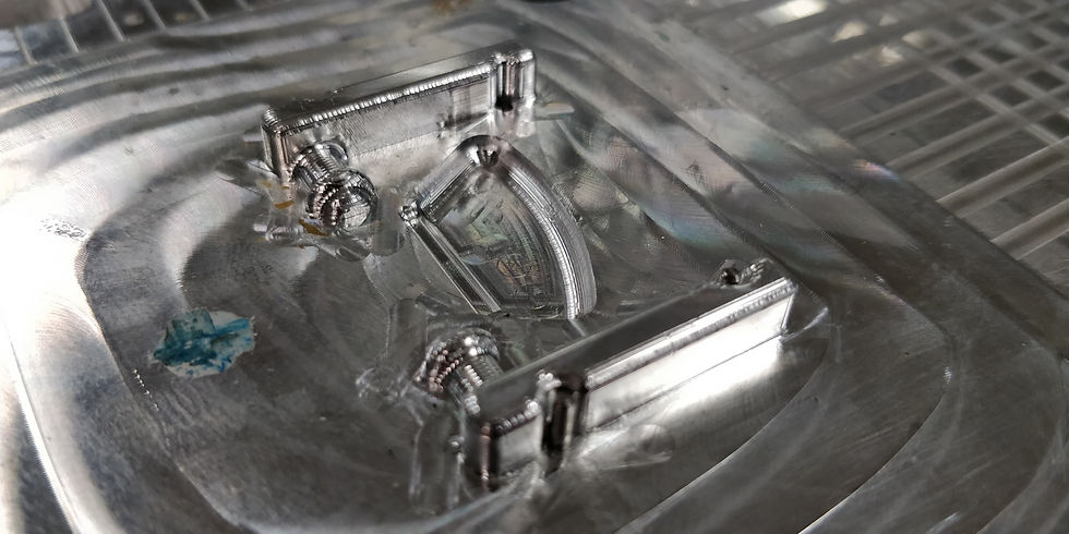

Similarly, the arms and mohawk mold were mapped out in strategic fashion. The mohawk, however, was manufactured as a solid body, due to its miniature nature, which is noticeable in our procedure as this is the only part of the mold with cavities on both halves.
Sink holes amongst other injection molding defects were avoided through accurate positioning of bosses and holes as well as uniform wall extrusion. It took our team a careful, iterative process of eliminating sharp corners to have our part approved for efficient CNC machining.
Runner design was done after laying out our parts onto the mold in Siemens NX Lab. Runner cross section geometry was determined from liquid resistance calculations. In order to reduce the amount of short shots or flashes during our injection it was key to file our gate to the correct size.

MANUFACTURING PROCESS
Following the completion of the computer aided drawing process, the computer aided manufacturing begins. Through the same software, Siemens NX, my team and I implemented manufacturing operations to machine our mold parts through the CNC Machine. Operation procedures include contour milling, with roughing and finishing utilizing various tool sizes and parameters ranging from ¾ Endmill to 1/16 inch ball mill. In order to have our desired finishes, whilst considering operation run time, we thoroughly refined our manufacturing operation process. After hours of training and evaluation, we were approved to use the CNC machine to mill our 2 pairs of molds. After the CNC milling, we were ready to use the injection molding machine, which was a much quicker process. We controlled temperature, injection pressure, time of injection to shoot rapid injection molded prototypes of our toy robot.
